We Drew This Electrical Plan 6 Times. Here's Why.
Apr 27, 2026We Drew This Electrical Plan 6 Times. Here’s Why.
What it actually takes to translate a client’s vision into construction documents a contractor can build from — on the most complex hi-fi listening room we have ever designed.
 This is the most complex electrical plan we have ever produced for a single room.
It took six drafts, a month of back-and-forth, and a client who knew more about hi-fi electrical theory than most licensed electricians will ever encounter in their career.
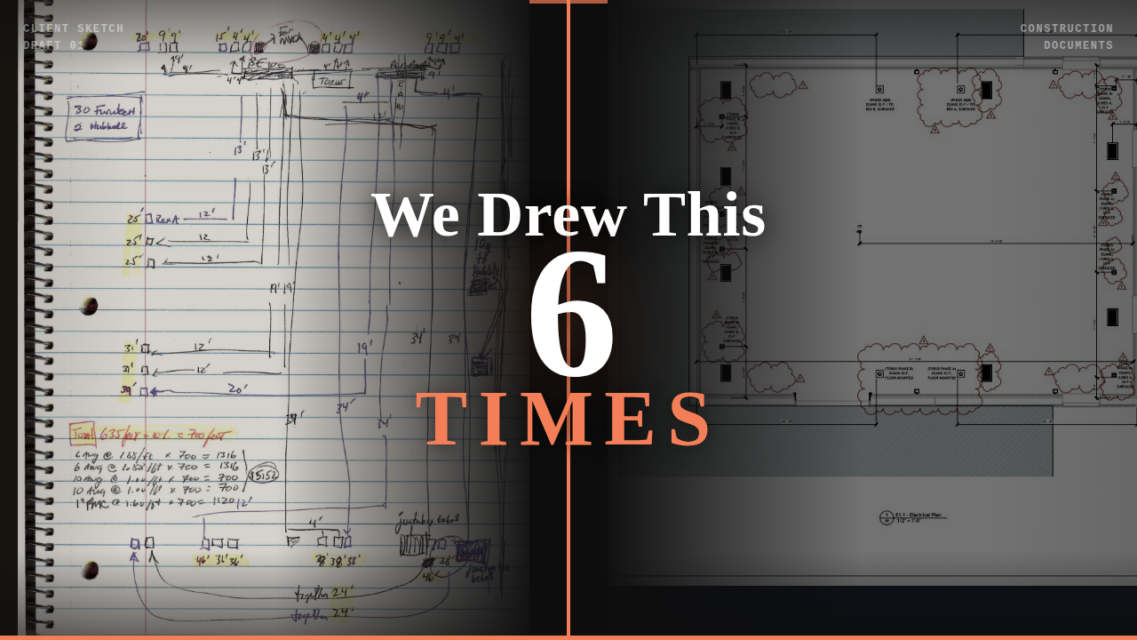
The drawings you are looking at above started as a notebook sketch. What sits in front of a contractor today is a fully coordinated Revit construction document with a dedicated power delivery chain, two panel systems, 32 receptacles, and 700 feet of wire specified to the gauge.
This is the story of how it got built on paper.
What This Room Actually Is 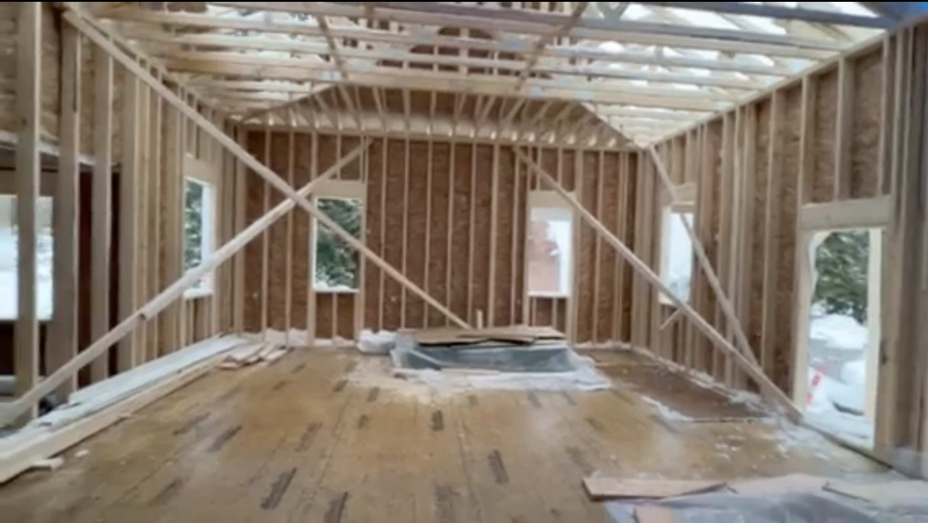
This is a dedicated hi-fi listening room designed to function as a private speaker showroom at the highest level of the hobby.
Sound isolation was engineered so that no external noise reaches the listening position. Not reduced. Not managed. Eliminated as a variable. When a speaker system costs what this one costs, the room cannot introduce uncertainty.
The build is currently in progress. Eventually this room will have acoustic clips and channel creating decoupled walls running independent of the structure around them. This is not acoustic treatment applied to a finished room. It is an isolated structural system engineered from the ground up.
The speakers that will eventually occupy this space represent a larger investment than the room itself. The room exists to make those speakers perform to their actual capability. That context matters when you read what follows about the electrical system.
The Client Arrived With a Vision We Had Never Seen Before 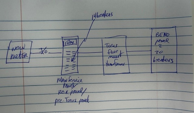
Most clients arrive with a general idea of what they want and rely on us to fill in the technical gaps. This client was different.
He arrived with a fully developed theory of how electrical infrastructure affects audio fidelity — one he had spent years researching and refining. He knew what he wanted down to the receptacle brand and wire gauge. What he needed was someone who could receive that level of specificity and translate it into something a contractor could actually build without guessing.
That is where we came in.
The first sketch he sent us showed the basic power delivery concept: a new dedicated utility line from the street feeding a custom panel, splitting into two paths, one going directly to receptacles and one passing through an isolation transformer before reaching a second panel. Simple enough to draw on notebook paper. Enormously complex to specify in full.
Over the following month we exchanged detailed email chains, reviewed hand-drawn charts, held Zoom calls, and worked through five intermediate drafts before reaching the final document. At each stage the client was marking up what we got wrong and we were iterating toward a specification that matched his vision precisely.
The drawings are the artifact of a collaboration. Not a deliverable we handed over. A record of a problem that had never been solved in exactly this configuration before.
That distinction matters. And it is what the six drafts represent.
Why the Electrical System Is Designed This Way 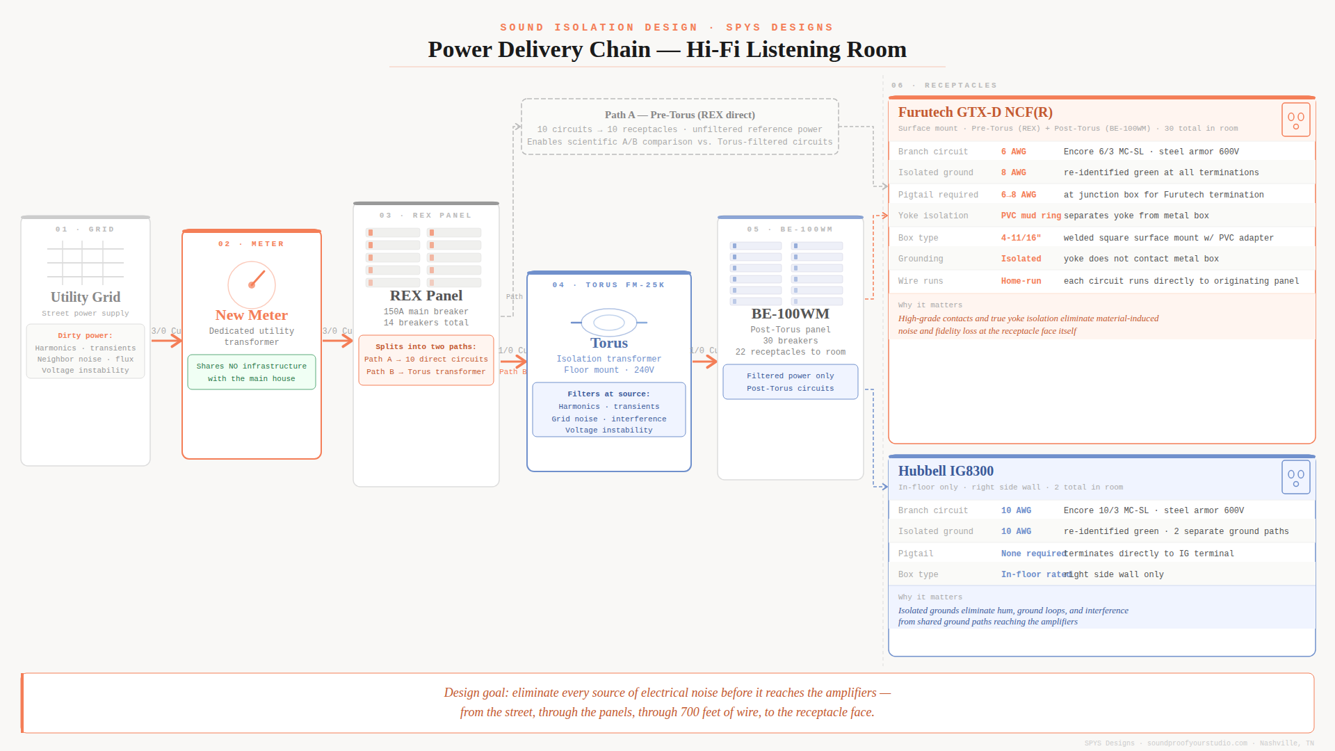
A word on framing before we get into the system. We are not hi-fi electrical engineers. We are sound isolation designers who worked alongside a client who is. What follows is our understanding of a system he designed, documented in construction drawings we produced. We are sharing it because it demonstrates something important about what design work actually looks like at this level.
- The dedicated utility line
The electrical system for this room does not share infrastructure with the rest of the house. A new dedicated utility transformer runs directly to a new meter that serves this system only.
Every appliance, light dimmer, and HVAC motor on a shared circuit introduces noise into the ground plane. At the level of amplification this system operates at, that noise matters. The dedicated line eliminates it at the source rather than attempting to filter it downstream.
2. The REX panel and the two-path split
Power arrives at the REX panel — a 150-amp main service panel with 14 breakers. From here the system divides into two distinct paths.
Path A feeds 10 circuits directly to 10 receptacles in the listening room. This is pre-Torus power — unfiltered, direct from the panel. These receptacles exist specifically so the client can compare source power against Torus-filtered power with near-scientific accuracy. This room is not just a listening room. It is a measurement environment.
Path B runs from the REX panel through 1/0 copper wire to the Torus isolation transformer before reaching a second panel. Everything downstream of the Torus is filtered.
3. The Torus isolation transformer
The grid delivers dirty power. Harmonics, transients, noise from neighboring properties, and voltage fluctuations all ride the line into your equipment. The Torus FM-25K sits between the panel and the downstream receptacles and filters that noise before it reaches the amplifiers.
At this investment level, the transformer is not an audiophile luxury item. It is infrastructure. Specifying it in the construction documents — with the correct wire gauge, panel connections, and physical installation requirements — is part of what makes the difference between a room that performs and one that almost performs.
4. The receptacle specification
The listening room contains 32 receptacles in total. Two types, each with a distinct specification.
Furutech GTX-D NCF(R) — 30 units, surface mounted in the floor. These are high-grade audiophile receptacles using rhodium-plated contacts and a non-coloring fiber body. Branch circuit wire is 6 AWG steel armor 600V. Isolated ground is 8 AWG re-identified green. Because the Furutech terminal cannot accept 6 AWG directly, the electrician must pigtail the 6 AWG to 8 AWG at the junction box. The yoke must be isolated from the metal box using a PVC mud ring adapter — a detail that is easy to miss and expensive to fix after drywall.
Hubbell IG8300 — 2 units, in-floor on the right side wall. Commercial-grade isolated ground receptacles. Branch circuit and ground both run 10 AWG, terminating directly to the IG terminal with no pigtail required.
Both types use isolated grounds. Neither allows the ground wire to terminate at the metal junction box. This eliminates the noise and ground loops that standard receptacles introduce by sharing a ground path with whatever else is connected nearby.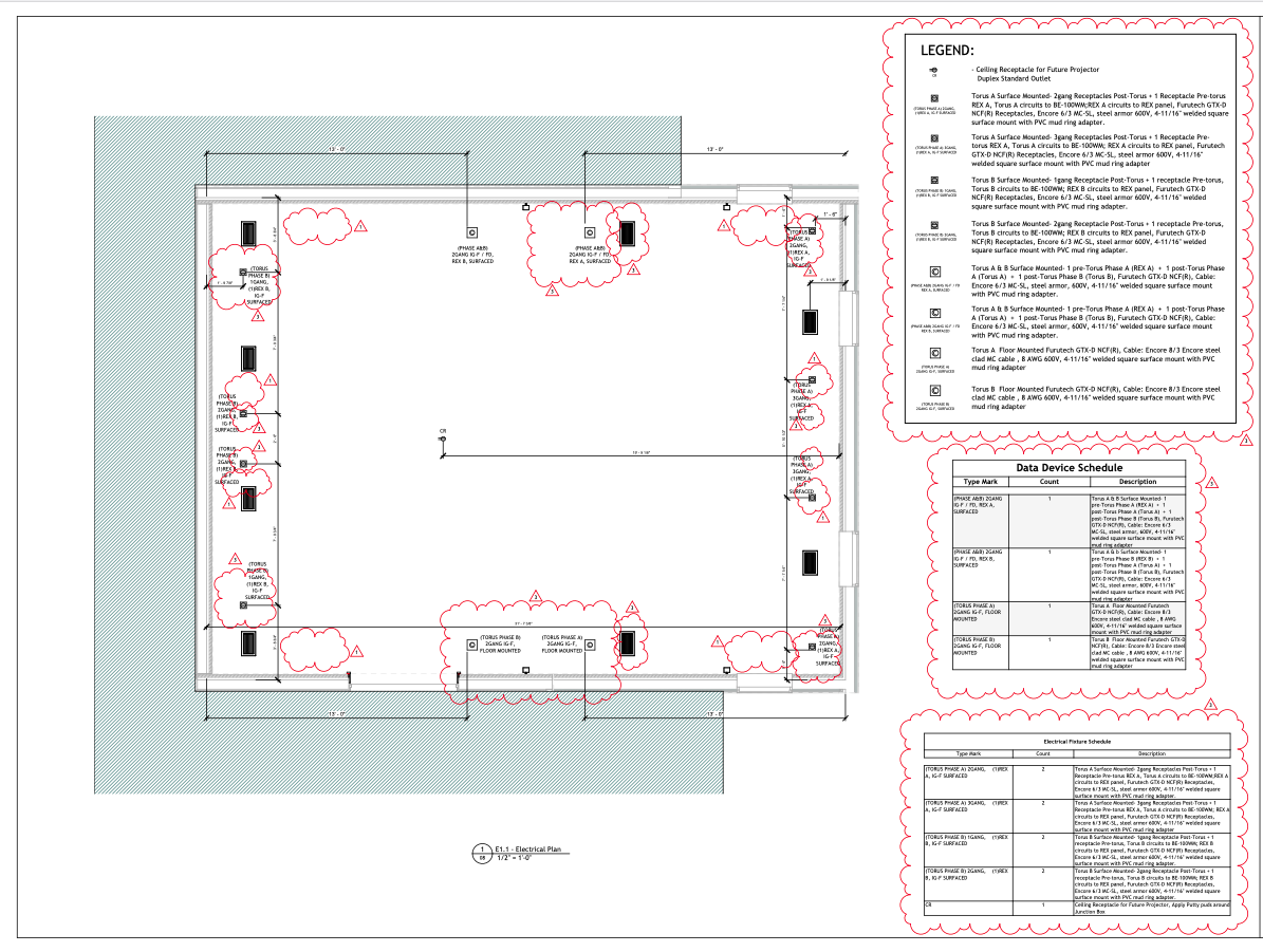
Six Drafts and What Changed 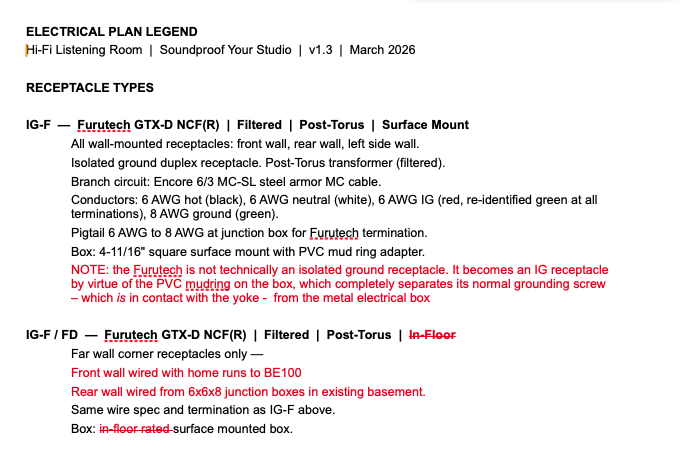
The final document did not arrive fully formed. It arrived through iteration.
The client’s initial sketches gave us the concept. Our first draft translated that concept into a structured document — circuit counts, panel labels, receptacle types. It came back with corrections. His redlines were precise: wrong panel designation here, incorrect circuit count there, a routing assumption that did not match his intent.
We revised. Sent it back. More corrections. This process repeated across six versions of the electrical legend alone, not counting the floor plan iterations happening in parallel.
What the redlines reveal is that getting this right required genuine back-and-forth, not a single pass. The client was not difficult. He was operating at a level of specificity that demanded a design partner who could keep up — who could ask the right questions, absorb the answers, and produce documentation that reflected his intent accurately enough for a contractor to execute without having to call anyone for clarification.
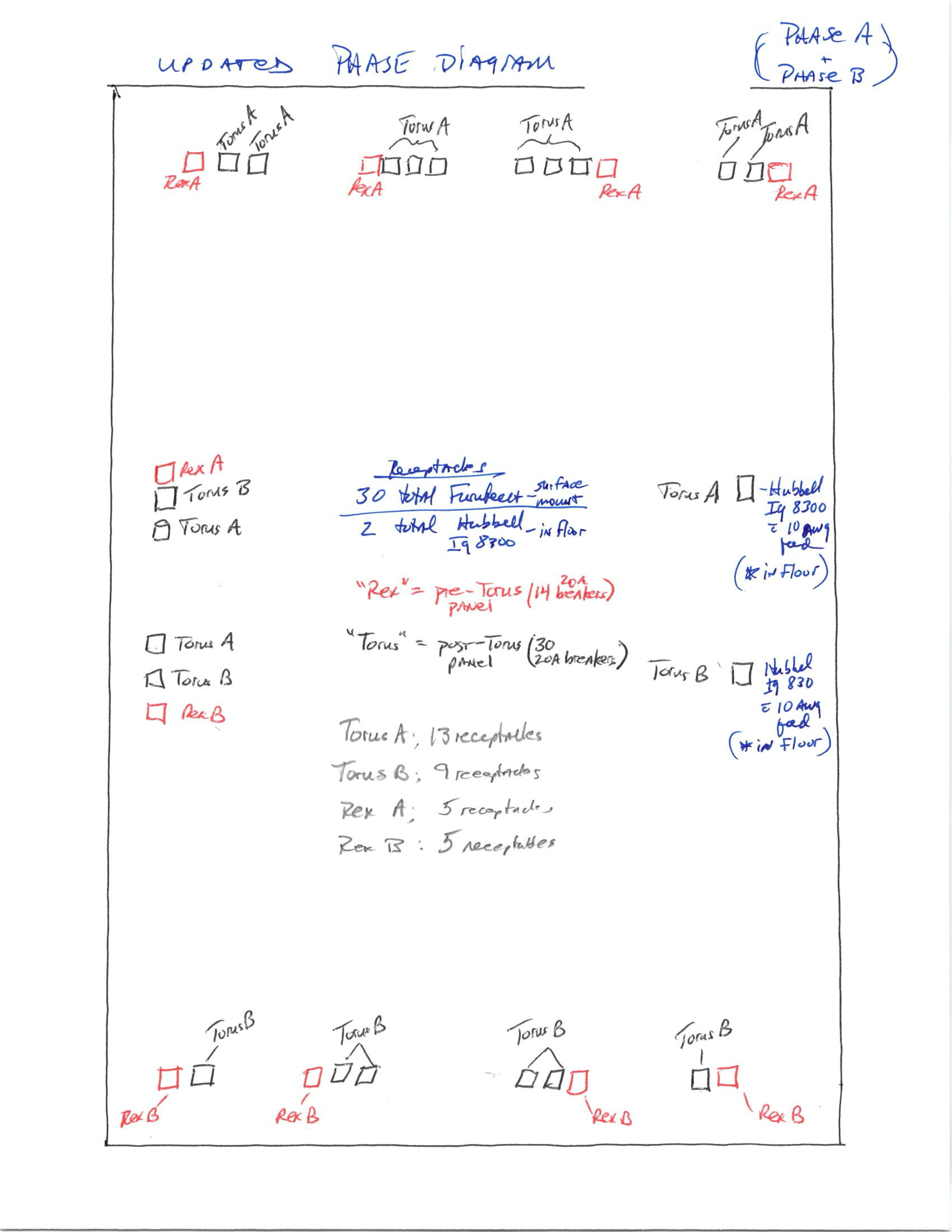
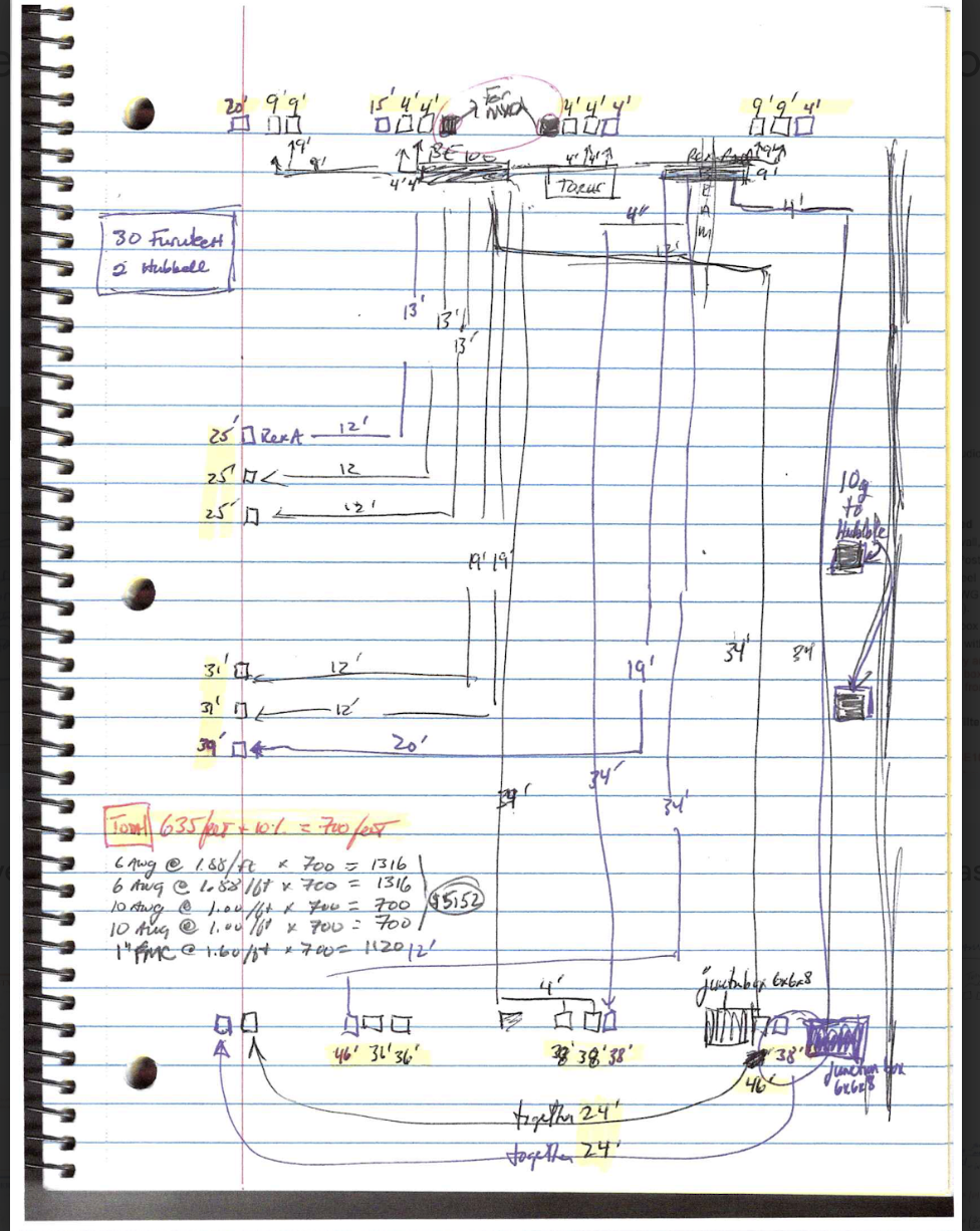
That phase diagram above is where the circuit classification was finally resolved. Torus A: 13 receptacles. Torus B: 9 receptacles. Rex A: 5 receptacles. Rex B: 5 receptacles. 32 total. It took multiple conversations and at least two drawing iterations to get the counts right and the routing logic clear.
Most people who talk about hi-fi rooms on the internet have never seen what it takes to get one built on paper. This is what it looks like.
What This Means If You Are Planning a High-Performance Room
Most electricians have never been handed a specification like this. Most designers would not know how to write one.
The gap between a client who knows exactly what they want and a contractor who can build it is a documentation problem. The client in this project had years of research and a clear vision. What he did not have was a set of construction documents that communicated that vision in the language of a building trade.
That is the problem sound isolation design exists to solve — not just for electrical systems, but for the structural assembly, the HVAC coordination, the flanking path control, and every other element that has to be engineered before the first stud goes up.
A design fee that surfaces a $75,000 scope gap is not a cost. It is the best money spent on the entire project.
If you are planning a dedicated listening room, a recording studio, or any high-performance space and you want to know what it actually requires — on paper, before construction starts — that is exactly what a Sound Isolation Site Assessment is for.
|
Is your project ready for this level of design? A Sound Isolation Site Assessment is the first step. Review your space, your goals, and your budget and learn exactly what a high-performance room requires before a single stud goes up. |
I’m Wilson Harwood, Sound Isolation Designer and Principal of SPYS Designs. We design sound isolated rooms all over North America.
Are you ready to move from planning to building?
Book a Soundproof Planning Call to determine whether your studio is feasible, what it will realistically cost, and what path makes sense for your space.
